TECHNICAL SUPPORT
-

-
Technical information
Principle of Variable Flow Meter
Principle of Rotameter ( Float Type) 1.
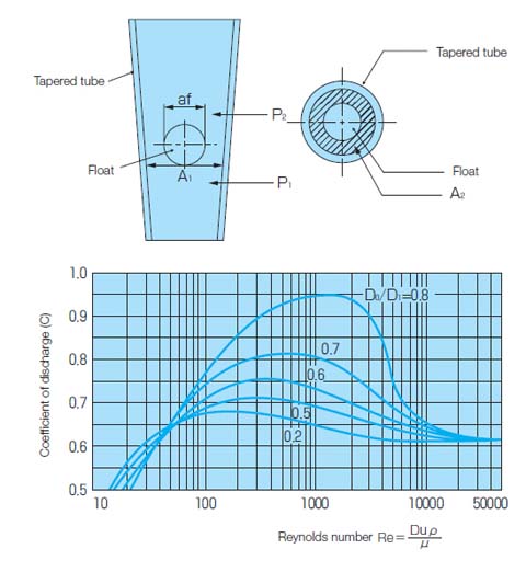
1. Figure
2.
The symbols and units are determined as follows:
Vf: Volume of float [cm3]
ρf: Density of float [g/cm3]
af: Maximum cross-section of float [cm2]
P1: Pressure directly under float [Pa]
P2: Pressure directly above float [Pa]
ρ: Flow density [g/cm3]
U1: Flow velocity directly under float [cm/sec]
U2: Flow velocity in float clearance [cm/sec]
A1: Cross section directly under float [cm2]
A2: Cross section of float clearance [cm2]
Q: Flow rate [cm3/sec]
g: Gravitational acceleration
3.
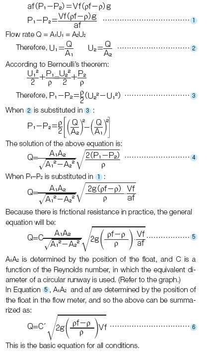
The force that pushes up the float is af (P1–P2).
Subtracting the buoyancy, the gravitation of the float is Vf (ρf–ρ) g.The balance equation is:
Principle of Rotameter ( Float Type) 【Example】
[In the case of a liquid]
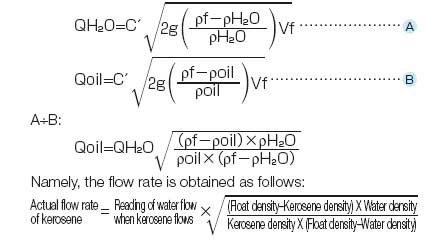
Equation 6 is used as it is. When a flow meter for water is used for kerosene with different specific gravity, the reading will change as follows:
[In the case of a gas]
In the case of a gas, the gas density ρ is negligibly small with respect to the float density ρf, and so Equation 6can be simplified as follows:
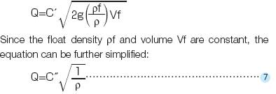
1.
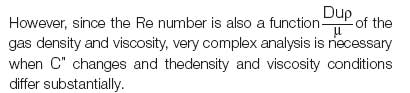
In the case of a gas, C" is regarded as constant when the Re number is close, and the flow rate is determined based on the gas density ρ.
2.
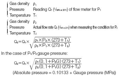
The gas density changes, of course, according to the type of gas, and it also changes according to the pressure and tem-perature. Therefore, when the same flow meter is used for measurement under different conditions, the following rela-tionship exists theoretically:
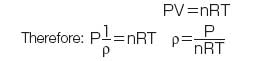
3.
The density is inversely proportional to the absolute temper-ature T, while it is proportional to the absolute pressure P. When these conditions are combined with Equation 7, the following equation holds:
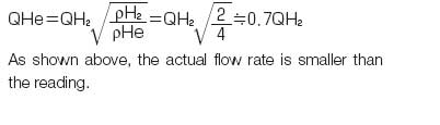
Example 1: When the type of gas differs
When a flow meter for H₂ is used for He, the equation will be as follows when the above equation is substitu-ted because P1, P2, T1, and T2 are the same:
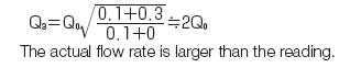
Example 2: When the pressure condition differs
When a flow meter for N₂ with the atmospheric scale (P1G = 0 Pa) is used for measurement of N₂ • 0.3 MPa (= P2G), ρ1, ρ2, T1, and T2 are the same and the follow-ing equation holds:
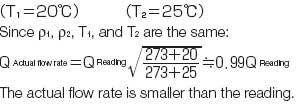
Example 3: When the temperature condition differs
When a flow meter calibrated at 1 atmosphere at 20°C is used at 25°C:
4.
The above corrections are approximations, and the meas-ured flow rate frequently differs from the theoretical value un-der actual conditions. Please use the correction equations, keeping in mind that theory and practice are not always the same.
Principle of Rotameter ( Float Type) 2.
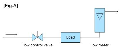
Flow rate when load pressure is applied (Measurement of gas)1.
As shown in Figure A, the fl oat type fl ow meter is generally used with the rear section of the fl ow meter exposed to the atmosphere or without any load (without pressure loss resistance).
The scale of such a fl ow meter is called "atmospheric scale."
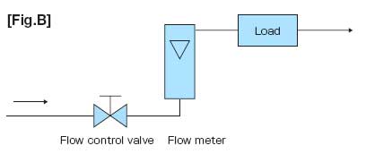
Flow rate when load pressure is applied (Measurement of gas) 2.
The scale of such a flow meter is called "atmospheric scale." In fact, however, there often exists load pressure resistance as shown in Figure B.
As shown in the example of the principle, load pressure resistance does not allow the actual flow rate to be indicated.
There is a method to find a rough standard using the equation for calculation, but some er-ror will be caused because of the gap between theory and practice.
Such an error will be caused both in the pressurized condition and in the vacuum condition.
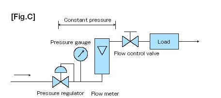
3.
For example, the flow control valve and the like are arranged in the later stage as shown in Figure C to control the pressure applied to the flow meter with a pressure regulator or the like.
The scale of the flow meter is calibrated under that pressure condition. The scale of such a flow meter is called a "load pressure scale."
An example of us-ing the load pressure scale is our GM Series gas mixing equipment. In the GM Series, the basic fl ow sheet is used as shown in Figure C so that the gas obtained with a constant flow rate will be pressurized.
The load pressure scale of a flow meter with a valve on the outlet side (needle, etc. on top of RK-1250) is automatically calibrated at all times, but if the flow meter will be used independently, please inform us of this in advance and select the Panotation.
An extra charge will be added for load pressure calibration.
Temperature correction
A scale, for which 20°C is used as the standard, is used frequently for area (float type) fl ow meters in general.
We also manufacture standard fl ow meters calibrated in a thermostatic chamber.
However, calibration at 0°C or some other temperature may be necessary according to the operating condi-tions.
In such cases, we manufacture a conversion scale as shown in example 3.(The calibration temperature is indicated on standard tapered tubes.)
Special scale of flow meter ( Rotameter )
1.
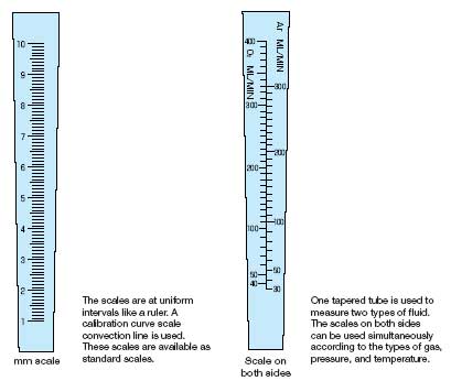
2.
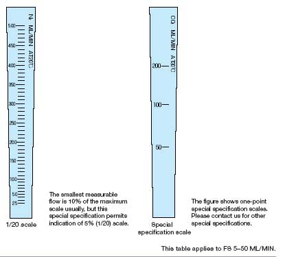
Scale notation on tapered tube of flow meter
Scale notation on tapered tube of flow meter
Flow meter with valve
By combining these two technolo-gies, we manufacture float type flow meters with various valves.
For flow control, the flow must be measured almost all the time.
Assem-bling a valve and a fl ow meter separately and then combining them may have some merits in terms of specifi cations, but fl ow meters with a valve have more merits in terms of piping labor, mounting space, and possibility of general adjustment.
To meet such needs, KOFLOC manufactures flow meters with vari-ous types of valves, as represented by the flow meter with a needle valve.
Flow meters with a needle valve are subdivided into the simple type, precision type, large-capacity type, and bellows type, as well as models with a valve on the inlet side or on the outlet side.
In addition, flow meters with a variable primary pressure type flow controller, flow meters with a variable secondary pressure type flow controller, and flow meters with a sophisticated control valve are also available.
Most valves attached to these flow meters are basically identical to the fl ow control valves shown under different headings.
Reference pages for those valves are shown in the text of the catalog. Please refer to those pages for the detailed specifications, etc.
Principle of Flow meter (Float Type) 3.
1.
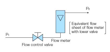
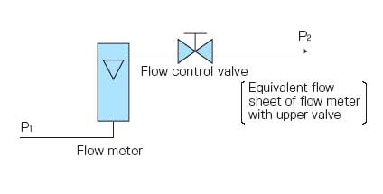
The equivalent flow chart of the upper and lower valves is shown in the figure.
The pressure loss of a flow meter is very small, not caus-ing any problem when a flow meter is used individually.
In the case of a flow meter with a valve, however, the inlet side pressure and outlet side pressure are important.
The valve installed in a flow meter causes a pressure loss, generating a difference between the inlet pressure and outlet pressure. As shown on page 50, the reading of a fl oat type flow meter differs according to the applied pressure.
There-fore, for flow meters with a valve, care is needed to see what will be the applied pressure.
In such cases, the inlet pressure P1 is throttled by a needle valve, changing into P2 at the outlet.
In the lower section, this P2 is the pressure applied to the flow meter. When there is no signifi cant load resistance (similar to atmospheric conditions) at the outlet and the subsequent section, P2 can be regarded as 0 MPa · G (gauge pressure), and as no pressure is applied to the flow meter, a general flow meter is used for calibration. (Refer to the atmospheric scale on page 50.)
Since operating pressure conditions are necessary for valves, however, it is necessary to clearly indicate P1 and P2when placing an order. Please indicate P2 as well when there is load resis-tance (when P2 pressure exist).
2.
In the case of the upper valve, the inlet pressure P1 is applied to the flow meter.
In that case, P1 and P2 are necessary when selecting a valve as mentioned above, and the scale of the flow meter should be the negative pressure scale (P.50) of P1.
Therefore, the pressure is controlled by a pressure regulator so that P1 will not change while us-ing a flow meter in general.
Especially, when pressure is reduced to a vacuum in the rear stage, the flow reading will be incorrect unless an upper valve type, which reduces pressure P1 so that the flow meter will not be decompressed, is used.
Care is needed.
Flow meter with flow controller
1.
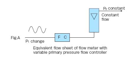
The variable primary pressure flow controller has a valve that controls the flow so that it will be constant even if the pres-sure on the primary side (inlet side) changes, and the flow meter is arranged as shown in Figure A.
In other words, this flow measuring control method is effective when P1 changes and P2 remains con-stant or is released to the atmosphere.
This flow meter with a valve is a lower valve type, because it meets the condition that the pressure applied to the fl ow measuring section should be constant.
2.
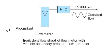
The variable secondary pressure flow controller can make the flow constant when the secondary-side pressure loss changes provided the primary pressure is constant.
It can be used in combi-nation with the flow meter as shown in Figure B. In the case of this valve, the primary pressure is constant, and it is used as an up-per valve as shown in the figure to control the pressure P1, which is applied to the flow meter, with a pressure regulator or the like.
There-fore, the flow meter scale is calibrated according to the scale in a state where pressure P1 is applied (load pressure scale).
Precautions for handling of flow meter
Measurement with area fl ow meter
When a float that moves up and down is put in a tapered tube that is precision-formed into a tri-flat and rib-guide and fluid is introduced from below, the fluid is throttled by the float, causing a pressure dif-ference before and after.Upon receiving an upward force due to this pressure difference, the float risesand stops at a position where it balances the effective weight of the movable section.
Since the relationship between the rising height, namely, the flow area, and the flow is constant, the po-sition is detected to measure the flow.
Precautions on handling of area fl ow meter
•Install the meter as vertical as possible in a dry place.
•Select pipes with appropriate material and diameter according to the fl uid, flow, and pressure.
•Thoroughly clean the inside of the pipe.
•Turn the mounted needle valve clockwise to decrease the fl ow, and turn it counterclockwise to increase the flow. (Refer to the precision needle valve Model 2412.)
•When stopping the flow with a needle valve, take great care that the axis does not turn beyond the flow stop position. (Refer to the preci-sion needle valve Model 2412.) Install a needle valve separately to keep it protected.
•The scale on the flow meter is marked according to the actual mea-surement.
•Refer to the fi gure below for reading the fl oat. (Refer to JIS Z8761.)
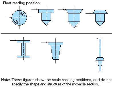
1.
•In order to prevent rupture of the tapered tube during fl ow measure-ment, do not let the pressure exceed 70% of the proof pressure. The temperature should not exceed 60°C to prevent breakage of the tapered tube and other parts. Use of toxic gas, toxic liquid, or any fluid other than those shown on the tapered tube or use at a tem-perature or pressure exceeding the highest limit could cause human injury. Never use the fl ow meter in such a manner.
•The clearance between the tapered tube and float is very small in our flow meters to enable very small flows to be measured. If dust or water enters the clearance, it will become clogged or unstable. Use clean and dry gas so that dust will not enter.
•Our original filter is installed within the very small flow range on the end face of the tapered tube. If an abnormality is found in the ta-pered tube, clean it with a neutral detergent. If the abnormality per-sists, contact us for recleaning.
•Should the needle valve cause trouble, return it as is to our company. We will investigate the cause and make adjustments.
•Install the flow meter perpendicularly. Contact us in advance if the flow meter is to be installed at an angle.
•Apply only the minimum force necessary to tighten nuts and screws.
2.
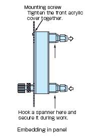
•Secure the flow meter joint (arrow section) with a spanner when mounting it on a panel or removing the pipe joint in order to prevent the joint from becoming loose. After mounting, be sure to conduct a leak test using soapy water.
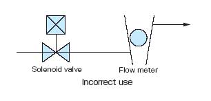
•If the pressure or flow changes suddenly, the fl oat will jump up, pos-sibly breaking the glass. When the fl ow meter is installed in series with a solenoid valve as shown in the fi gure, a fairly large quantity of gas will flow suddenly. Install a regulator or the like in between to iso-late the fl ow meter from direct pressure change.
•N₂ conversion or air conversion is used for calibration. In principle, however, the accuracy will not be guaranteed unless the actual gas is used. When accuracy is particularly important, it is recommended to use the actual gas.
For calibration with any gas other than our standard gases, a separate gas cylinder is necessary. Provide us with the actual gas or we will prepare the gas by ourselves (an extra charge and actual gas calibration charge will be required). However, if dangerous gases are to be used or the flow rate is too large, we may not be able to assist, in order to protect our products and facili-ties. Contact our sales representative in advance.
Mounting and piping (General specifi cations)
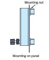
Mounting and piping (General specifi cations) 2.
•Use the accompanying nuts as shown in the figure when installing the flow meter on a panel. Refer to the dimensional drawing for the panel process-ing method.
If you find any unclear point concerning the mounting, con-tact our factory.
Mounting and piping (General specifi cations)
•Connect a piping joint to the gas inlet and outlet so that no load will be applied to the flow meter.